TURZX 3.5" Smart Screen / A Reverse Engineering Attempt Gone Wrong

Do not disassemble this display unless you are prepared to risk permanently damaging the LCD.
The LCD panel is extremely fragile, and the enclosure uses tiny screws with a construction that makes separating the assembly surprisingly difficult.
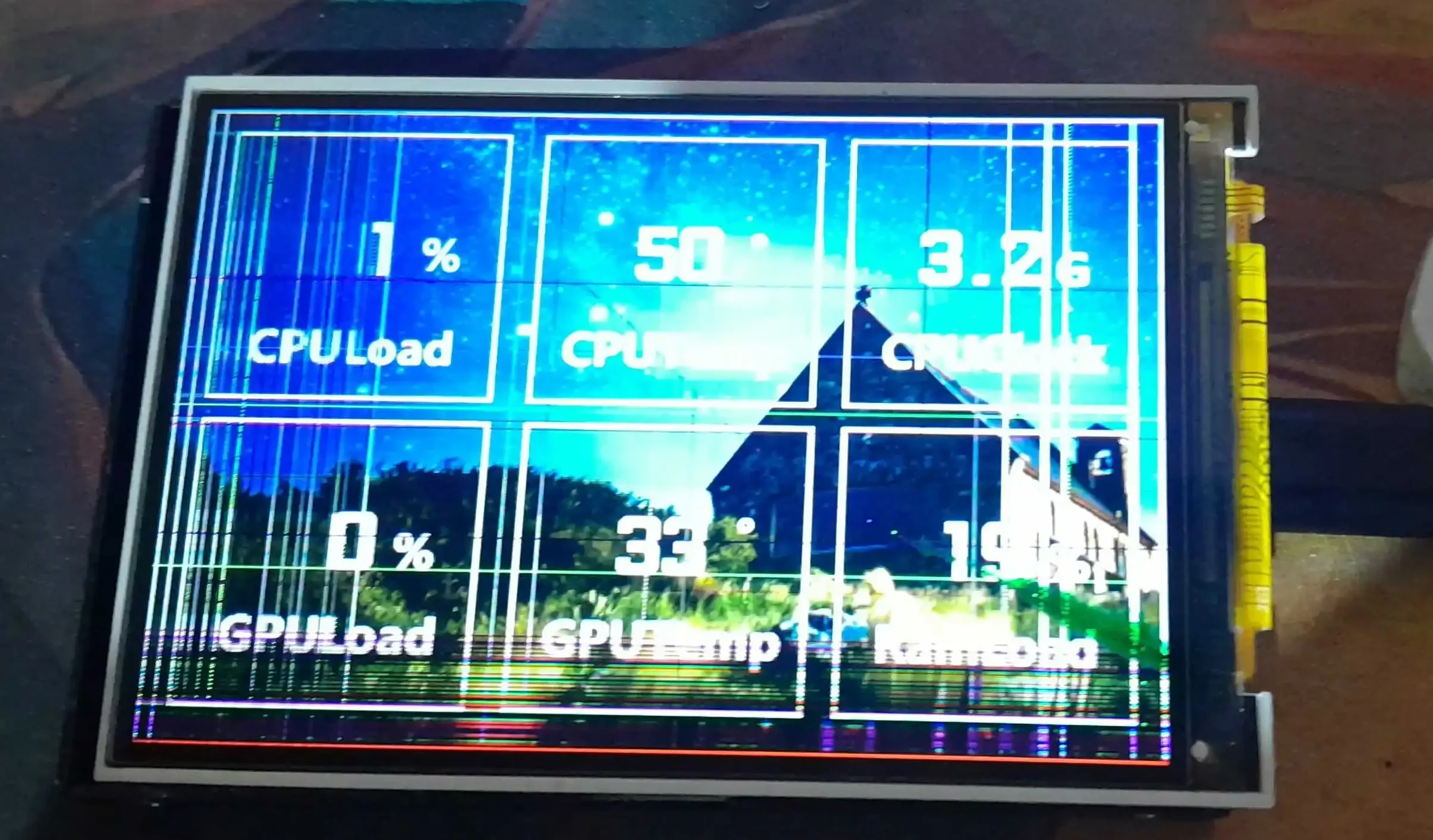
I ended up cracking the display while trying to open it.
This post is documenting that mistake specifically so someone searching for TURZX 3.5" disassembly, Turing Smart Screen teardown, USB35INCHIPSV2, or VID_1A86&PID_5722 sees this warning before making the same mistake.
Recently, I bought a TURZX / Turing Smart Screen 3.5-inch to use as a small secondary telemetry display for my PC.
Like many inexpensive hardware devices, the configuration software that comes with it doesn't have a Linux version.
Yes, I know about the open-source project turing-smart-screen-python. I actually tested it and, surprisingly, it worked partially with my screen. However, some things didn't work correctly, which made me suspect that perhaps my model used some small hardware or protocol variation.
So, naturally, I started reverse engineering it to find out how it actually worked and, hopefully, add full support for my model.
Everything was going reasonably well.
I was reading the turing-smart-screen-python source code and matching it against the packets sent by the official software using Wireshark. Little by little, some things started to make sense.
Until I had the brilliant idea of opening the screen so I could see and document the internal components.
And, of course, that didn't go very well.
Yeah.
The screen was way too fragile, and I ended up damaging the LCD during disassembly.
So, instead of a complete teardown, this post ended up becoming a mix of hardware documentation, some protocol findings, and a warning to prevent someone else from making exactly the same mistake I did.
The Device
The device is sold under names such as:
- TURZX 3.5" Smart Screen
- Turing Smart Screen 3.5"
- Turing Smart Screen
USB35INCHIPSV2
The PCB itself is branded:
Turing Smart Screen
图灵智显
www.turzx.com
The USB device identifies itself as:
VID: 1A86
PID: 5722
Identifier: USB35INCHIPSV2
These identifiers were particularly useful during the reverse engineering process because they made it possible to distinguish the display from the other USB devices connected to my computer.
Before Opening It
Before touching the hardware, I decided to understand as much as possible through software.
The first step was simply capturing the communication between the official application and the display.
Using Wireshark, I noticed a surprisingly large amount of USB traffic being generated while the screen was running.
There were many packets like:
URB_BULK OUT
URB_BULK IN
and some sequences repeatedly appeared with sizes such as:
531 bytes
531 bytes
531 bytes
3849 bytes
At first, this looked like complete chaos.
There were so many packets being generated that trying to inspect them one by one was basically useless. The important part was isolating the traffic from the actual display and then looking at the payload rather than the USB traffic as a whole.
A Strange Pattern in the Payload
Once I started looking at the actual data being transmitted, I noticed several repeating values:
6e5b f7b5 f7b5 f7b5 f7b5 ...
6e5b 6e5b 6e5b 6e5b ...
ffff ffff ffff ffff ...
The data looked suspiciously like 16-bit pixel values.
That immediately made me think about RGB565, since the display is handling graphical data and RGB565 is a widespread format for small LCDs.
For example, RGB565 represents each pixel using 16 bits:
RRRRRGGGGGGBBBBB
So completely different colors produce values such as:
FFFF
0000
F800
07E0
001F
for white, black, red, green, and blue respectively.
I hadn't completely decoded the protocol at this point, so I wasn't ready to say that the entire transfer was simply raw RGB565 data.
But there was definitely something interesting there.
Looking at the Software
This is where the existing open-source implementations became extremely useful.
Instead of trying to reverse engineer everything from scratch, I could compare the packets captured from the official software with the code from turing-smart-screen-python.
That turned the investigation into a much more manageable problem.
Rather than asking:
"What does this giant stream of bytes mean?"
I could ask:
"This function is supposed to send an image. Do the bytes generated here match what I see in Wireshark?"
That is a much nicer question.
And, unlike staring at thousands of hexadecimal bytes, it occasionally has answers.
Opening the Device
After getting a reasonable understanding of the software side, I decided that seeing the PCB would make the investigation easier.
I wanted to document:
- the main microcontroller;
- the USB interface;
- the power circuitry;
- the LCD connector;
- and any other identifiable components.
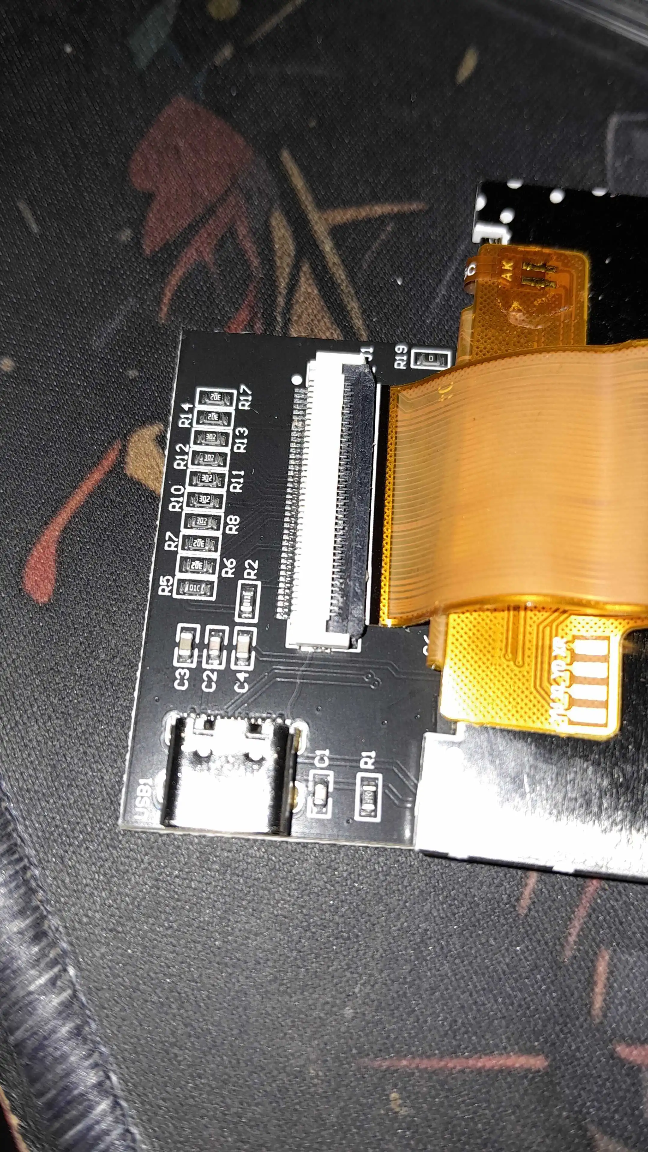
The PCB itself is actually quite interesting for such a small device.
The board contains a CH552T microcontroller and an AMS1117-3.3 voltage regulator, along with the usual resistors, capacitors, USB connectors, and the LCD connector.
CH552T
The CH552T is the most interesting component on the board.
Considering that the USB device identifies itself as:
VID: 1A86
PID: 5722
and that the board contains a WCH CH552T, it is very likely that this microcontroller is responsible for the USB side of the device.
That gives us a basic architecture that looks something like:
Computer
   │
   │ USB
   ▼
CH552T
   │
   │ display data
   ▼
LCD circuitry
   │
   ▼
IPS panel
I still haven't completely mapped the connections between the CH552T and the LCD controller, so this is intentionally a simplified view rather than a complete schematic.
AMS1117-3.3
The other obvious IC is an AMS1117-3.3.
Its job is much less mysterious: it provides a 3.3 V supply for the board.
So the power path is approximately:
USB 5V
   │
   ▼
AMS1117-3.3
   │
   ▼
3.3V
   │
   ├── CH552T
   └── other circuitry
Nothing particularly exotic here, but it is useful information when documenting the hardware.
The LCD Connector
The LCD is connected through a very fine-pitch FPC connector.
And this was the point where I probably should have stopped.
The connector itself wasn't particularly difficult to identify.
Actually separating the display assembly from the enclosure was the problem.
The screws are tiny, the construction is tight, and there is very little room to apply force without transferring that force directly into the LCD.
I tried anyway.
Several times.
That was a mistake.
The Failure
Eventually, I cracked the LCD.
The display still showed an image, but it was obviously damaged, with severe artifacts and lines across the panel.
At that point, continuing the physical teardown made no sense.
The whole purpose of opening the device was to learn more about the hardware.
I had already learned that the hardware was fragile.
Mission achieved, I suppose.
Just not in the intended way.
What I Would Do Differently
Looking back, the correct order should have been almost the opposite of what I did.
I should have:
1. Identify the USB device
2. Capture the communication
3. Reverse engineer the protocol
4. Inspect the existing open-source implementations
5. Document the PCB externally
6. Only then consider opening the enclosure
There was never really a reason to physically disassemble the display before understanding the protocol.
The software was already providing most of the useful information.
And unlike the LCD, software doesn't crack when you look at it aggressively.
Hardware Information
Here is what I was able to document before the display became a casualty:
Product:
TURZX / Turing Smart Screen 3.5"

USB VID:
1A86

USB PID:
5722

USB Identifier:
USB35INCHIPSV2

Microcontroller:
WCH CH552T

Voltage Regulator:
AMS1117-3.3
The PCB is also marked:
Turing Smart Screen
图灵智显
www.turzx.com
What Remains to Be Investigated
There is still quite a bit that I didn't get to finish.
The most interesting parts are probable:
- the exact USB protocol;
- the packet structure;
- whether the image data is really RGB565;
- how the image is divided into the
531and3849byte transfers; - the initialization sequence;
- and the exact interface between the CH552T and the LCD.
The existing Python implementation should make most of this considerably easier to investigate.
Unfortunately, my particular LCD is no longer in a state where repeatedly experimenting with it is a good idea.
The Important Part
If you're reading this because you're about to search for how to open a TURZX 3.5" Smart Screen, stop here for a moment.
You probably don't need to open it.
The LCD panel is extremely fragile, and the mechanical construction makes it surprisingly easy to damage.
At the very least, capture the USB communication and inspect the software first.
There is a great chance you'll learn more from the USB packets and the existing software than you would by taking the enclosure apart.
And you'll still have a functional screen afterward.
I unfortunately chose the other branch of the decision tree.
Recources
Descriptor
Bus 003 Device 002: ID 1a86:5722 QinHeng Electronics UsbMonitor
Couldn't open device, some information will be missing
Device Descriptor:
  bLength                18
  bDescriptorType         1
  bcdUSB               2.00
  bDeviceClass            2 Communications
  bDeviceSubClass         0 [unknown]
  bDeviceProtocol         0
  bMaxPacketSize0        64
  idVendor           0x1a86 QinHeng Electronics
  idProduct          0x5722 UsbMonitor
  bcdDevice            1.00
  iManufacturer           1 Turing
  iProduct                2 UsbMonitor
  iSerial                 3 USB35INCHIPSV2
  bNumConfigurations      1
  Configuration Descriptor:
    bLength                 9
    bDescriptorType         2
    wTotalLength       0x0043
    bNumInterfaces          2
    bConfigurationValue     1
    iConfiguration          0
    bmAttributes         0xa0
      (Bus Powered)
      Remote Wakeup
    MaxPower              500mA
    Interface Descriptor:
      bLength                 9
      bDescriptorType         4
      bInterfaceNumber        0
      bAlternateSetting       0
      bNumEndpoints           1
      bInterfaceClass         2 Communications
      bInterfaceSubClass      2 Abstract (modem)
      bInterfaceProtocol      1 AT-commands (v.25ter)
      iInterface              0
      CDC Header:
        bcdCDC               1.10
      CDC Call Management:
        bmCapabilities       0x00
        bDataInterface          0
      CDC ACM:
        bmCapabilities       0x02
          line coding and serial state
      CDC Union:
        bMasterInterface        0
        bSlaveInterface         1
      Endpoint Descriptor:
        bLength                 7
        bDescriptorType         5
        bEndpointAddress     0x81  EP 1 IN
        bmAttributes            3
          Transfer Type            Interrupt
          Synch Type               None
          Usage Type               Data
        wMaxPacketSize     0x0008  1x 8 bytes
        bInterval             255
    Interface Descriptor:
      bLength                 9
      bDescriptorType         4
      bInterfaceNumber        1
      bAlternateSetting       0
      bNumEndpoints           2
      bInterfaceClass        10 CDC Data
      bInterfaceSubClass      0 [unknown]
      bInterfaceProtocol      0
      iInterface              0
      Endpoint Descriptor:
        bLength                 7
        bDescriptorType         5
        bEndpointAddress     0x82  EP 2 IN
        bmAttributes            2
          Transfer Type            Bulk
          Synch Type               None
          Usage Type               Data
        wMaxPacketSize     0x0040  1x 64 bytes
        bInterval               0
      Endpoint Descriptor:
        bLength                 7
        bDescriptorType         5
        bEndpointAddress     0x03  EP 3 OUT
        bmAttributes            2
          Transfer Type            Bulk
          Synch Type               None
          Usage Type               Data
        wMaxPacketSize     0x0040  1x 64 bytes
        bInterval               0
Photos


Final Warning
The LCD is much more fragile than the PCB.
If you are planning to disassemble a TURZX / Turing Smart Screen 3.5", assume that the LCD can crack during the process.
Do not use force against the panel or its edges.
I started this project wanting to understand how the display worked.
I ended it with a better understanding of the hardware, some interesting USB traffic, a partially documented protocol, and a cracked LCD.
At least now there is documentation warning the next person.
Hopefully they find this page before opening theirs.